Makebase MKS PI and TS-35 Case
Description
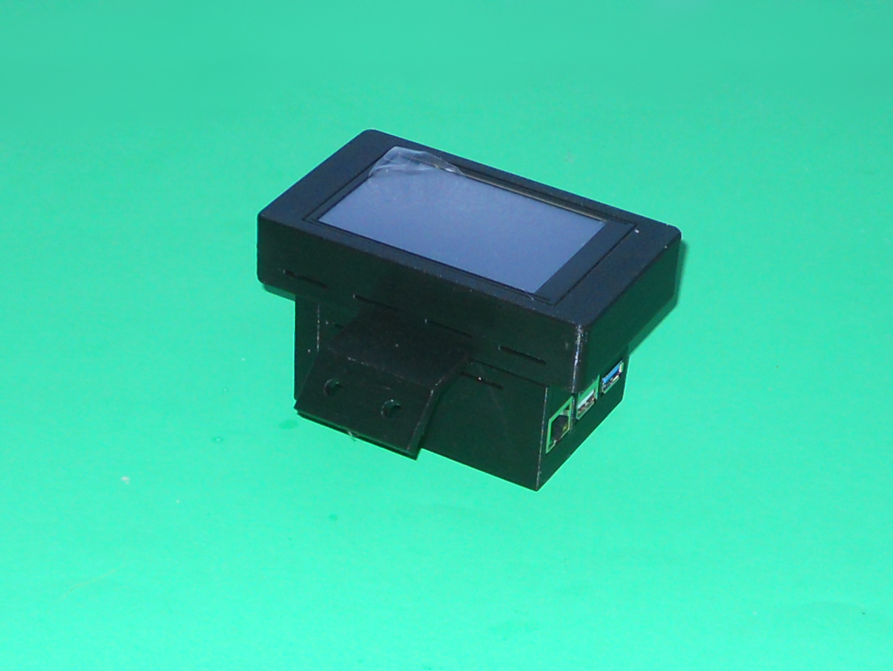
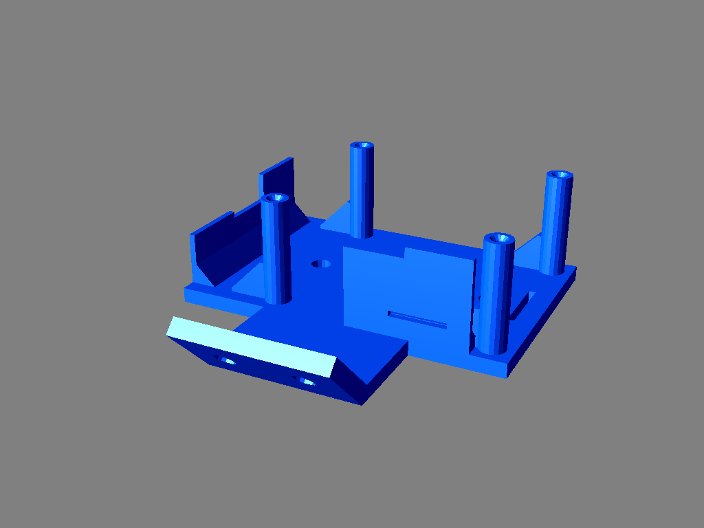
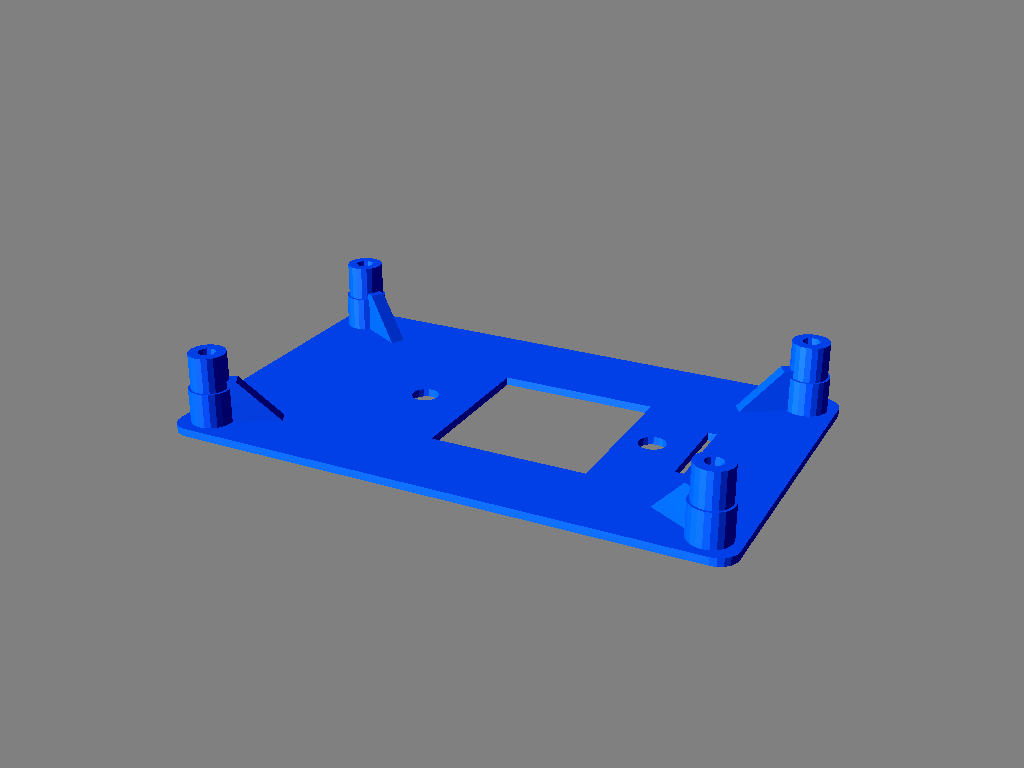
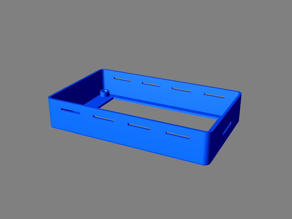
This is a single case for the MKS PI and the TS-35 display running Klipper from MakerBase. This case combines the MKS PI board and the display into a single module.
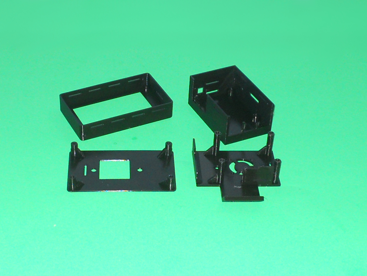
Support material is not required to print the 4 required parts. An infill of 20% is recommended. For the CPUBoardTopPlateVertical, an 25% infill, 6 top bottom, 6 top layers and 3 verticals layer are recommended. This part needs to be sturdy.
You'll need the following hardware to assemble it:- Four M5 x 10 mm screws- Two M5 T-nuts- Two M5 nuts- Four M3 x 15 mm screws- Four M2.5 x 10 mm screws- Optionally a 30 mm x 8 mm fan
Some of the screws can be replaced with some glue or may be substituted. Do not overtighten the screws.
Make sure that the connector of the screen is on your left when the display is set at its final position. This will ensure that the content of the display is upright.
The four printed parts should be assembled in this order:
-
The ScreenBackPlate and the CPUBoardTopPlateVertical must be assembled first. Put both flat sides against each other. The holes in each of them must be aligned. Use two M5 x 10 mm screws along with two nuts. The CPUBoardTopPlateVertical part shall be centered relative to the ScreenBackPlate.
-
Put the TS-35 screen in the bezel named ScreenBezelNoBrassInserts. Install the bezel on the ScreenBackPlate. Make sure that the screen connector is above the slot in the bezel. Pass the end of the flat cable in the slot. I suggest putting the unused length in the bezel. Handle the flat cable with care. It is fragile. Use four M3 x 15 mm screws to attach the screen bezel to its base.
-
Connect the power cable to the MKS PI.
-
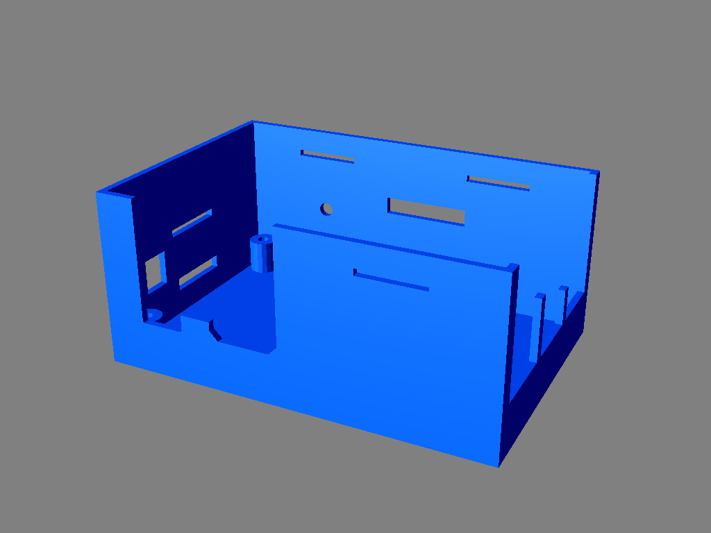
Put the MKS PI into the CPUBoardMainBody. Remove the uSD card before doing so. Attach it to its top plate using four M2.5 x 10 mm screws.
-
Use two M5 x 10 mm screws along with two T-nuts to mount the module on the printer. It was designed to be mounted on aluminum extrusion.
This object was designed using Solid Edge Community Edition.
Files
|
|
CPUBoardMainBody.stl |
|
|
CPUBoardTopPlateVertical.stl |
|
|
ScreenBackPlate.stl |
|
|
ScreenBezelNoBrassInserts.stl |
This object is also published on the following site(s):
The source files are available
You may request the source file(s) for this object by posting a comment below. Your email address will be used solely to deliver the requested source files and for no other purpose.
By requesting the source files, you are granted permission to:
- Share — Copy and redistribute the material, excluding the source files, in any medium or format.
- Adapt — Remix, transform, and build upon the material.
By requesting the source files, you also agree to:
- Give appropriate credit, provide a link to the license, and indicate whether changes were made. You may do so in any reasonable manner, provided it does not suggest that the licensor endorses you or your use.
- Not use the material for commercial purposes.
- Distribute any derivative works under the same license as the original if you remix, transform, or build upon the material.
- Not apply legal terms or technological measures that legally restrict others from exercising the rights granted by this license.
- Not upload the source files or modified versions of the source files to any website or file-sharing service. They are provided for your personal use only. However, you may freely upload and distribute any STL or OBJ files generated from them.
If you do not agree to all of these conditions, please do not request the source files.
Copyright 2012–2026, Claude "Tryphon" Théroux