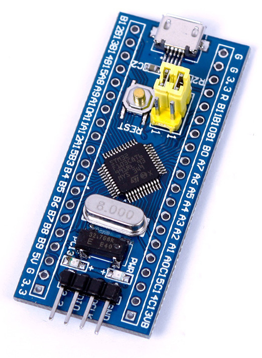
STM32 Minimum System Development Board
This post describes how to upload code to a STM32 Minimum System Development Board that can be bought from Ali Express or eBay for around $4.00 US. You will be able to compile and upload a led blinking program to the board at the end of this guide. This guide is using Arduino_STM32 by Roger Clark.
You will need:
- to download Roger Clark’s Arduino IDE STM32 board support files. It can be downloaded from this link.
- to download the latest Arduino IDE. It can be downloaded from this link.
- a USB to TTL Serial Cable that uses 3.3V signal level such as link or any equivalent cable.
The setup steps are:
- First, install the Arduino IDE following the provided instructions.
- Install Arduino SAM Boards (32 bits ARM Cortex-M3) using the Arduino IDE option Tools -> Board -> Boards Manager.
- Locate the hardware folder within the Arduino IDE installation folder.
- Un-archive the STM32 support files in the hardware directory found in the Arduino IDE installation folder. Rename the top folder Arduino_STM32-master to Arduino_STM32. If you restart the Arduino IDE, you will find in the Tools -> Board option a new set of boards including the STM32F103C Series.
- Connect the TTL Serial Cable ground pin to one of the ground pins of the board labeled G. It is the black wire on the picture below. The TTL Serial Cable shall be disconnected from the PC at this stage.
- Connect the TTL Serial Cable 5V to the pin labeled 5V on the board. It is the red wire on the picture below. A 3.3V supply can also be used. In this case, connect the 3.3V supply to a pin labeled 3.3 on the board.
- Connect the TTL Serial Cable RX pin to the board A9 pin. It is the white wire on the picture below.
- Connect the TTL Serial Cable TX pin to the board A10 pin. It is the green wire on the picture below.
- Set the jumpers. Boot0 shall be set to 1 (HIGH) and Boot1 to 0 (LOW). The Boot1 jumper is right beside the reset switch.
- Plug the TTL Serial Cable to the PC. A red led should light up on the board indicating that it is powered.
The board setup looks like this using an Adafruit 954 TTL Serial Cable.

In the Arduino IDE:
- Create a new sketch (File -> New).
- Copy the code below. It will make the onboard led blink.
- Select the board Generic STM32F103C Series from the Tools -> Board option.
- Select STM32F103C8 (20k Ram, 64 k Flash) from Tools -> Variant option.
- Select Serial from the Tools -> Upload method option.
- Select the port of the TTL Serial Cable from the Tools -> Port option.
- Verify the sketch (Sketch -> Verify/Compile).
- Hit the reset button on the board and wait 4 seconds. If you do not wait enough, you will get a “Failed to init device.” message.
- Upload the sketch to the board (File -> Upload). You will get a bunch of messages. The last line will be “Starting execution at address 0x08000000… done.”.
- The green led will now blink.
If you reset the board or unplug it, your program will not run unless you set both Boot0 and Boot1 jumpers to 0 (LOW).
The test sketch is:
void setup() {

pinMode(PC13, OUTPUT);

}
void loop() {

digitalWrite(PC13, HIGH);

delay(100);

digitalWrite(PC13, LOW);

delay(100);

}
hi i tried your method but i keep getting failed to upload..any clue?
…Chip was locked, wrote the compiled blink .bin or .hex (cant remember) using ST’s Flash Loader Demonstrator. http://www.st.com/en/development-tools/flasher-stm32.html (at the bottom)
Now its blinking. Thanks.
C:\Program Files (x86)\Arduino\hardware\Arduino_STM32/tools/win/serial_upload.bat COM11 {upload.altID} {upload.usbID} C:\Users\User\AppData\Local\Temp\arduino_build_560096/STM32F103C8_Blink.ino.bin
Got NACK from device on command 0x43
Can’t initiate chip erase!
Failed to erase memory
stm32flash 0.4
http://stm32flash.googlecode.com/
Using Parser : Raw BINARY
Interface serial_w32: 230400 8E1
Version : 0x22
Option 1 : 0x00
Option 2 : 0x00
Device ID : 0x0410 (Medium-density)
– RAM : 20KiB (512b reserved by bootloader)
– Flash : 128KiB (sector size: 4×1024)
– Option RAM : 16b
– System RAM : 2KiB
Write to memory
Erasing memory
Can u make a video?
Do ur led blinks 6 times when u press reset?
Blinks forever.