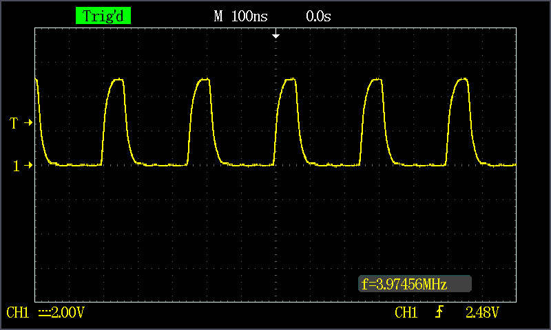
What is the maximum frequency an Arduino can generate? Typically, I obtained a frequency of less than 100 kHz using the Arduino function calls. The results were lower than I expected. I also observed that I had a frequency higher by 25 kHz using a pin from the 8 to 13 pin set than a pin from the 0 to 7 pin set. These tests yield a virtually perfect waveform. I obtained almost 4 MHz by accessing the register directly. The waveform was not as good as the waveform of the first four tests. The waveform is given in Figure 1.

Sketch 1 Frequency: 72.6 kHz
Duty Cycle: 47.7%
#include

#define OUTPUT_PIN 3

void setup() {
  pinMode(OUTPUT_PIN, OUTPUT);
}

void loop() {
  digitalWrite(OUTPUT_PIN, HIGH);
  digitalWrite(OUTPUT_PIN, LOW);
}

Sketch 2 Frequency: 74.3 kHz
Duty Cycle: 49.2%
#include

#define OUTPUT_PIN 3

void setup() {
  pinMode(OUTPUT_PIN, OUTPUT);
}

void loop() {
  while(1) {
    digitalWrite(OUTPUT_PIN, HIGH);
    digitalWrite(OUTPUT_PIN, LOW);
  }
}

Sketch 3 Frequency: 96.94 kHz
Duty Cycle: 49%
#include

#define OUTPUT_PIN 8

void setup() {
  pinMode(OUTPUT_PIN, OUTPUT);
}

void loop() {
  digitalWrite(OUTPUT_PIN, HIGH);
  digitalWrite(OUTPUT_PIN, LOW);
}

Sketch 4 Frequency: 96.94 kHz
Duty Cycle: 49%
#include

#define OUTPUT_PIN 8

void setup() {
  pinMode(OUTPUT_PIN, OUTPUT);
}

void loop() {
  while(1) {
    digitalWrite(OUTPUT_PIN, HIGH);
    digitalWrite(OUTPUT_PIN, LOW);
  }
}

Sketch 5 Frequency: 3.97 MHz
Duty Cycle: 25.6%
#include

void setup() {
  DDRB = B00000001;
}

void loop() {

  while(1) {
    PORTB = 0xff;
    PORTB = 0x00;
  }
}

Click on the image to improve the quality.

Wave generated by modifying directly the port
Figure 1: Waveform generated by modifying directly the port (Sketch 5)

Leave comment

Your email address will not be published. Required fields are marked with *.

Time limit is exhausted. Please reload the CAPTCHA.