
Ikea Bror Caster Holder V02
This object lets you install casters to a Bror workbench. This is a new version of my previous design ( http://www.ctheroux.com/ikea-bror-caster-holder/ ). It is more robust. This design was inspired
Read More
Sterilite 2051LAB8 Drawer Separator
This is a separator for the Sterilite 2051LAB8 plastic drawer. The drawer units have a capacity of 5.7 l. The drawer units are 32.7 cm deep x 22.5 cm in
Read More
Spray can holder for pegboard
This is a spray can holder for pegboards (1 in x 1 in pegs) with 20 degrees angle. Support material that touches the build plate is required. An infill of
Read More
ASUS VA32A Monitor Storage Add-On set 2
These are some add-ons for the ASUS VA32A Monitor Storage. It includes small part trays. The ASUS VA32A Monitor Storage project is located at http://www.ctheroux.com/asus-va32a-monitor-tray-system/ . Print them at a
Read More
Office Tool Caddy
This is a simple tool caddy for the desk in my office. Support material is not required. An infill of 20% is recommended. This object was designed using Solid Edge
Read More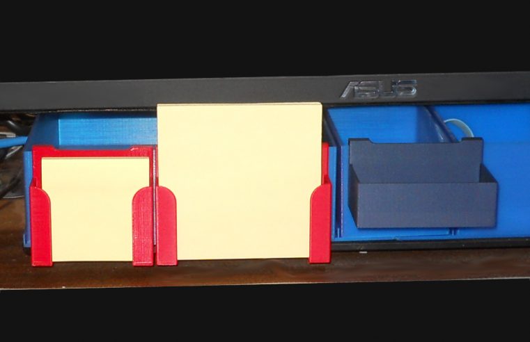
ASUS VA32A Monitor Storage Add-On set 1
These are some add-ons for the ASUS VA32A Monitor Storage. It includes Post-IT holders and a small part tray. It can hold 2 inches x 2 inches and 3 inches
Read More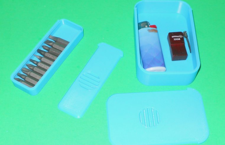
Altoids Tins Like Parametric Containers
This is a script that generates Altoids Tins like parametric containers. You need to put all the files into a directory to generate your own containers. Copy one of the
Read More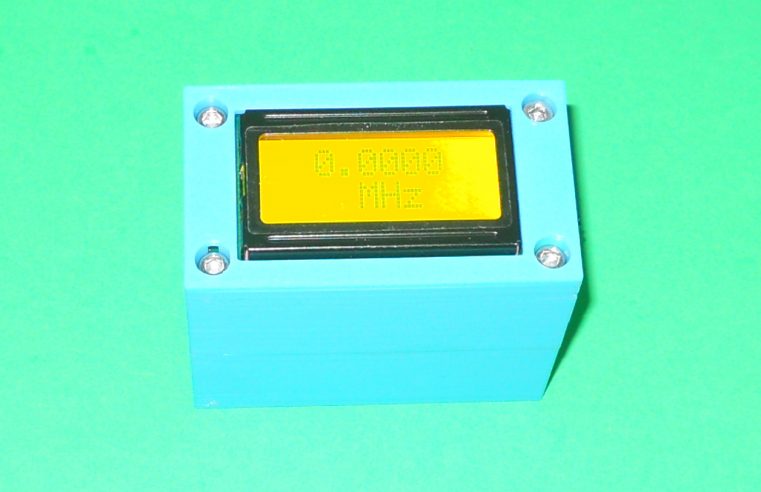
Frequency Counter Case
This is a case for a frequency counter widely available on discount Chinese sites such as https://www.aliexpress.com/item/1005006203286595.html?spm=a2g0o.order_list.order_list_main.66.61291802TVURcl . Some assembly is required. 4 M3 x 8 mm hex cap screws
Read More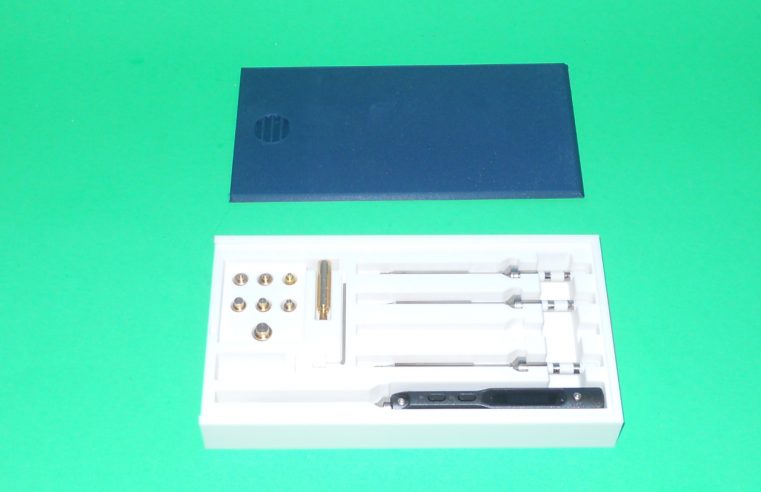
TS-100 Case V2
This is a case for a TS-100 soldering iron along with 4 tips and threaded insert iron tip kit. The threaded insert iron tip kit can be bought on AliExpress
Read More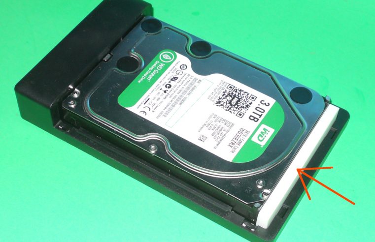
Parametric Square Spacer
This is a simple parametric square spacer. Support material is not required. An infill of 15% is recommended. This object was designed using openSCAD. Printable Files Parametric Square Spacer
Read More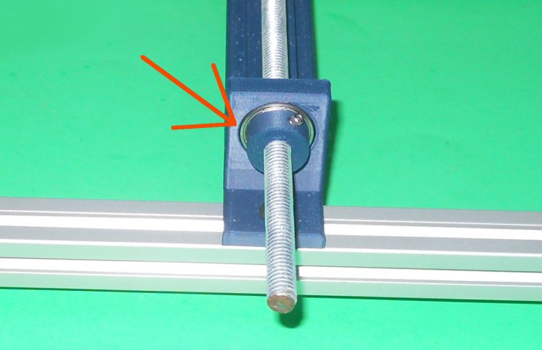
Parametric Shaft Lock
This is an object used to lock a shaft. Its design is parametric. It is recommended to use a brass insert to hold the grub screw. Support material is not
Read MoreArduino UNO R4 Wi-Fi password connection issues
The Arduino UNO R4 Wi-Fi is a great addition to the Arduino family. A fun little board to play with. The Arduino UNO R4 Wi-Fi could not connect to my
Read More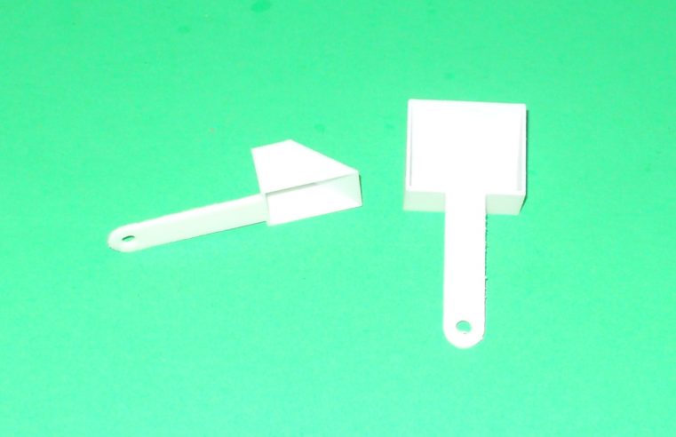
Parametric Scoop
This parametric model creates scoops. Support material is optional. An infill of 20% is recommended. This object was designed using openSCAD. Printable Files Parametric Scoop model 15mm x
Read More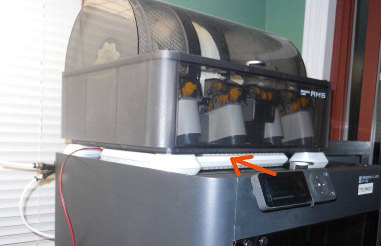
Bambu Lab Top LED Strip
This is an object that holds LED strips to be installed on the top glass of a Bambu Lab printer. Even if the light goes through the top glass, it
Read More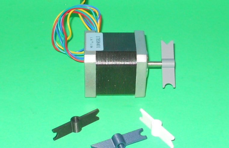
5 mm D Shaft Flag
This is a rotation indicator for a 5 mm D Shaft as found on Nema 17 motor for example. It is used as a diagnostic tool. Support material is not
Read More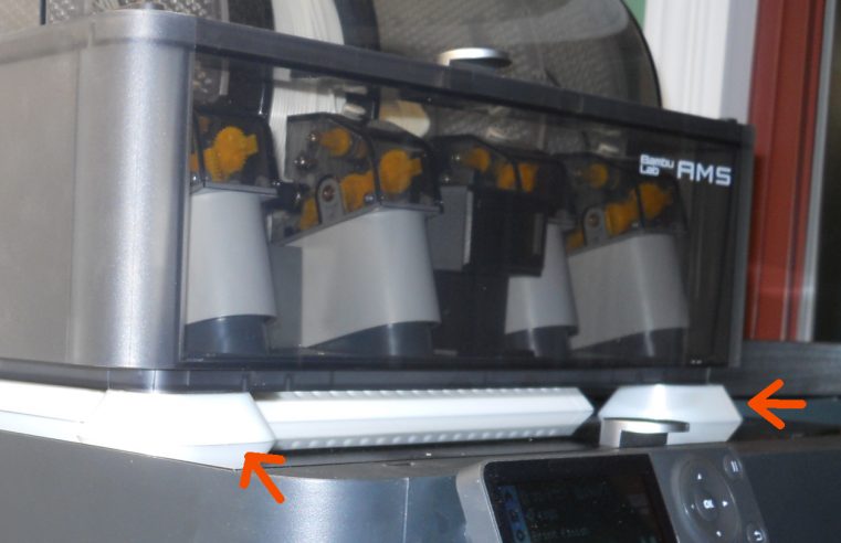
Bambu Lab AMS Riser Feet
This is an object that rises the Bambu Lab AMS by 14 mm. It was design to insert some led strip between the top printer glass and the AMS unit.
Read More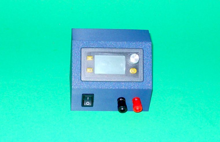
XY-SK80H Buck Boost Converter Case
This is a case for a XY-SK80H Buck Boost Converter. It fits many different models having this form factor (39mm x 71.3 mm). You’ll need the following to assemble it:
Read More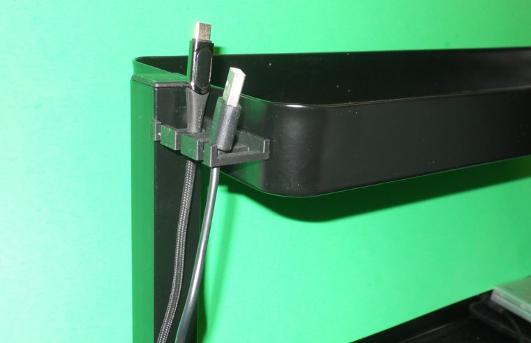
Ikea Vattenkar Cable Holder
This is a cable holder for the Ikea Vattenkar organizer. A M3 x 6 mm nut and bolt or equivalent are required for assembly. Support material is not required. An
Read More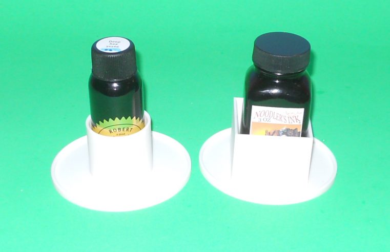
Parametric Bottle Stabilizer
This is a bottle stabilizer parametric model. For now, it contains the configuration for Robert Oster and Noodle’s ink bottles. Support material is not required. An infill of 20% is
Read More